|
|
|
Usuarios conectados
Actualmente hay 6040 visitantes online. |
|
Productos
|
|
Información
|
|
Destacado
|
|
|
 |
|
|
No hay comentarios de productos.
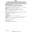
CONNECTIONS (Fig. 2 � Fig. 10)
12
CH-3
(L)
34
CH-1 CH-1+3
�
5
CH-2
7
�
8
REMOTE
9
GND
+
CH-1
+
25A 25A
BATTERY
Before making connections, be sure to turn the power off to all audio components. Connect the yellow battery lead from the amp directly to the positive (+) terminal of the vehicle's battery. Do not connect this lead to the fuse block. To prevent external noise from entering the audio system. � � Locate the unit and route the leads at least 10 cm away from the car harness. Keep the battery power leads as far away from other leads as possible.
INPUT
(R)
OUT
(R) (L)
CH-4
CH-2
CH-2+4
� CH-4 �
+
� CH-3 BRIDGED
+ +
SPEAKER OUTPUT
25A
PRE
7 Battery Lead Terminal 8 Remote Turn-on Lead Terminal 9 Ground Lead Terminal - Insulation Tube a Battery Lead (Yellow) Be sure to add a 5 50 amp fuse (or two 25A fuses in parallel) as close as possible to the battery's positive (+) terminal. This fuse will protect your vehicle's electrical system in case of a short circuit. If you need to extend this lead, the wire gauge should be 8 AWG or larger. 5 MRV-F505 ... 50 amp fuse (or two 25A fuses in parallel) MRV-F405 ... 40 amp fuse (or two 20A fuses in parallel) MRV-F305 ... 30 amp fuse b Remote Turn-On Lead (Blue/White) Connect this lead to the remote turn-on or power antenna (positive trigger, (+) 12V only) lead of your head unit. c Ground Lead (Black) Connect this lead securely to a clean, bare metal spot on the vehicle's chassis. Verify this point to be a true ground by checking for continuity between that point and the negative (�) terminal of the vehicle's battery. Ground all your audio components to the same point on the chassis to prevent ground loops.
FUSE
POWER SUPPLY
(MRV-F505)
�
6 a b c
25A
Secure the ground lead to a location connected to the car�s chassis. Make sure this spot is free from dirt, grease or paint to insure a good connection. � If you add an optional noise suppressor, connect it as far away from the unit as possible. Your Alpine dealer carries various noise suppressors, contact them for further information. � Your Alpine dealer knows best about noise prevention measures so consult your dealer for further information. 1 , 2 RCA Input Jacks (CH3/4), (CH1/2) Connect these jacks to the line out leads on your head unit using RCA extension cables (sold separately). Be sure to observe correct channel connections; Left to Left, Right to Right, Front to Front and Rear to Rear. 3 , 4 RCA Pre-out Jacks (CH1+3), (CH2+4) 5 , 6 Speaker Output Terminals (CH1/2), (CH3/4) The MRV-F505/MRV-F405/MRV-F305 has two sets of speaker outputs. Be sure to observe correct speaker output connections and phasing. In the stereo mode, connect the right speaker outputs to the right speaker and the left to left. Connect the positive output to the positive speaker terminal and the negative to negative. In the bridged mode, connect the left positive to the positive terminal on the speaker and the right negative to the negative terminal of the speaker. Do not use the speaker (�) terminals as a common lead between the left and right channels. Do not connect this lead to the vehicle's chassis ground. NOTE: Do not connect speaker leads together or to chassis ground.
d
e
f
g
h
i
j
k
l
m
1
ST
1+2
OFF
ON
X1
X20
OFF
ON
3
ST
3+4
OFF
ON
OFF
ON
X1
X20
1/2
3/4 1+3/2+4 NOM
4V
INPUT MODE
LP
HP
INPUT MODE
LP
HP
INPUT CHANNEL INPUT LEVEL
CHANNEL-1/2
CHANNEL-3/4
4/3/2 CHANNEL POWER AMPLIFIER MRV - F505
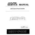
SWITCH SETTINGS
The switch modes shown are for CH1/2. Same explanations apply to mode selection for CH3/4. d Input Mode Selector Switch a) Set to the "ST" position (center) when the two channels are used in stereo.
1 ST 1+2
n
o
p
NOM 0.5V
CHANNEL-1/2 150/3K 150 100/2K 200/4K 100 200 70/ 1.4K 50/1K 300/ 70 6K (Hz) 400/8K 50 300 (Hz) 400 MIN
The CH-1 (or CH-2) input will output at the Speaker Output Terminal CH-1 (or CH-2). b) Set to the "1" position when the two channels are used for one channel of a stereo bridged system. c) Set to the "1 + 2" position when the two channels are used for a subwoofer
l Input Channel Selector Switch a) Setting this switch to 1/2 will send the signal at the inputs of CH1/2 to CH3/4 1/2 3/4 1+3/2+4 of the MRV-F505/MRV-F405/MRVF305. This eliminates the need for "Yadaptors when using a head unit with a single pair of pre-amp output. b) Set this switch to 3/4 to have the inputs of CH3/4 accept independent input 1/2 3/4 1+3/2+4 signals. An example of this application would be the use of a head unit with dual pre-amp outputs. c) Setting this switch to 1 + 3/ 2 + 4 will sum the CH1 and CH3 input and send 1+3/2+4 it to CH3 while the CH2 and CH4 inputs are summed and sent to CH4. When used with a dual-preamp output head unit, this will provide a non-fading (constant bass) subwoofer output with fadable front and rear output going to a separate Satellite amplifier. m Input Level Selector Switch Set to the "4V" position when the head unit with 4V output voltage is used. When the head unit with non-4V output voltage is used at the "4V" position, the volume will be decreased. n , r Crossover Frequency Adjustment Knob When the frequency multiplication switch is set to the "X1" position, the crossover frequency can be adjusted in the range of 50 to 400Hz. When the frequency multiplication switch is set to the "X20" position, the crossover frequency can be adjusted in the range of 1k to 8 kHz. o , q Crossover Frequency Adjustment Knob Permits adjustment of the crossover frequency, by rotating the knob to select any frequency between 50 to 400 Hz as the crossover point. p , s Input Gain Adjustment Control Set the MRV-F505/MRV-F405/MRV-F305 input gain knobs to the minimum (4V) position. Using a loud cassette or preferably a CD as a source, slowly turn up the head unit volume until you just hear the sound distort. At that point, reduce the volume one step so the distortion is no longer audible. Keep head unit output at this level and begin increasing the amplifier gain until the maximum output level you desire is reached. To prevent damage to the speakers or amplifier, the maximum output level should not cause bottoming of the speakers or excessive distortion of the amplifier.
MAX
1
ST
1+2
LP
100 70 50 150 200
HP
150/3K 100/2K 200/4K 300/ 6K
GAIN
NOM 0.5V
1 ST 1+2 1/2 3/4
300 70/ 1.4K (Hz) 400
system which uses the right channel and left channel signals summed.
50/1K (Hz) 400/8K MIN CHANNEL-3/4
MAX
q
r
s
V12
DC STRAIGHT
e , i Crossover Mode Selector Switch a) Set to the "ON" position when the amplifier is used to drive a subwoofer. OFF ON The frequencies above the crossover point will be attenuated at 12 dB/ octave. b) Set to the "OFF" position when the amplifier will be used for driving fullOFF ON range speakers. The full frequency bandwidth will be output to the speakers with no high or low frequency attenuation. f , k Frequency Multiplication Switch a) "X1": Normal crossover frequency (50 to 400Hz)
X1 X20
5
b) "X20": The crossover frequency will be multiplied by 20 (1k to 8 kHz).
X1 X20
Fig. 2
5 When adjusting the knobs n � s , remove two hexagon screws by using the hexagon wrench (M2) included and remove the cover. 5 Lors du réglage des boutons n � s , déposer les deux vis à six pans à l'aide de la clé à vis hexagonale (M2) fournie et déposer le couvercle. 5 Cuando ajuste los botones n � s , retire los dos tornillos hexagonales utilizando la llave hexagonal (M2) proporcionada y quite la cubierta.
g , j Crossover Mode Selector Switch a) Set to the "ON" position when the amplifier is used to drive a tweeter/ midrange system. The frequencies OFF ON below the crossover point will be attenuated at 12 dB/octave. b) Set to the "OFF" position when the amplifier will be used for driving fullrange speakers. The full frequency
OFF ON
bandwidth will be output to the speakers with no high or low frequency attenuation. h Input Mode Selector Switch a) Set to the "ST" position (center) when the two channels are used in stereo. 3 ST 3+4 The CH-3 (or CH-4) input will output at the Speaker Output Terminal CH-3 (or CH-4). b) Set to the "3" position when the two channels are used for one channel of a 3 ST 3+4 stereo bridged system. c) Set to the "3 + 4" position when the two channels are used for a subwoofer system which uses the right channel and left channel signals summed.
3
ST
3+4
|
|
|
> |
|